imrishabh18/pedometer
This code defines and assembles a simple radio receiver hardware circuit using specific imported capacitors, inductors, RF connectors, and oscillator components with precise footprints and schematic attributes.
- Version
- 1.1.3
- License
- unset
- Stars
- 0
review/footprint-fix-verification.json
PCB
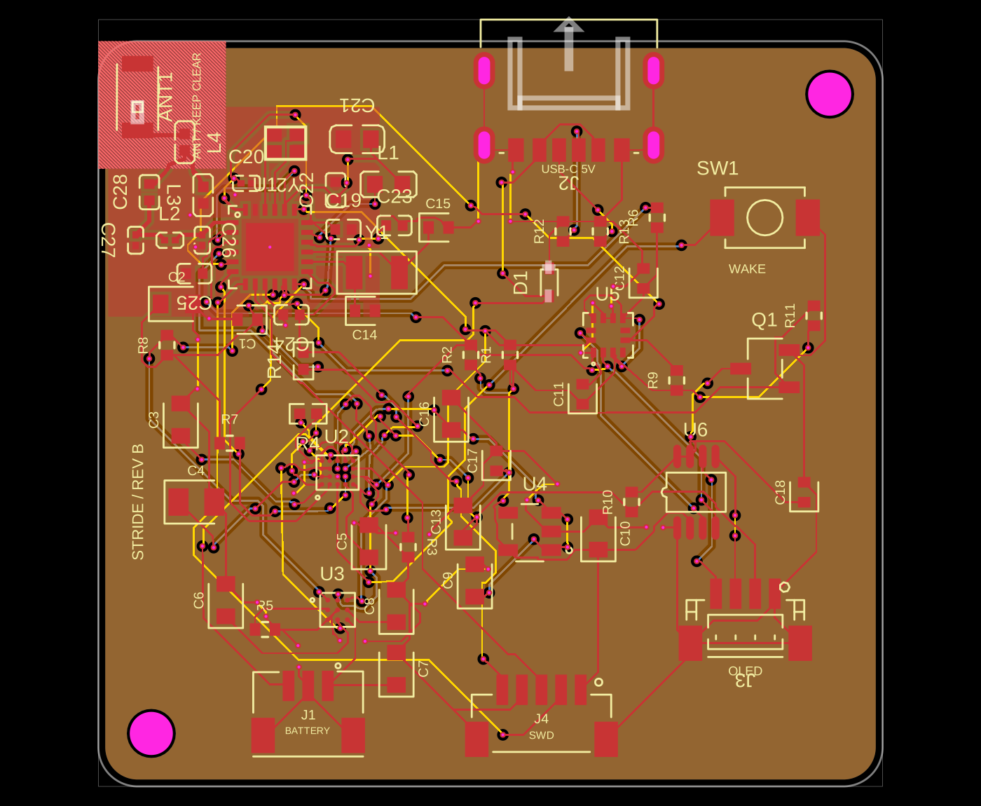
Schematic

{
  "localVersion": "1.1.3",
  "registryPublished": false,
  "circuitSha256": "384dff968fe32973bb6b1736216a0d754ce44283f269d087da7546204ef430cd",
  "build": "PASS",
  "typecheck": "PASS",
  "tsciCheck": {
    "errors": 0,
    "warnings": 0
  },
  "drc": {
    "build": 0,
    "placement": 0,
    "routing": 0,
    "unconnectedPorts": 0,
    "missingSourceTraces": 0,
    "discontinuousTraces": 0
  },
  "shorts": "PASS",
  "tests": {
    "passed": 18,
    "failed": 0,
    "assertions": 1042
  },
  "exactImportedFootprints": {
    "components": 16,
    "pads": 32,
    "result": "PASS"
  },
  "exportedPassivePads": {
    "copperMaskPaste": 32,
    "result": "PASS"
  },
  "bom": {
    "components": 62,
    "groupedRows": 40,
    "allHaveJlcpcbCodes": true
  },
  "cpl": {
    "components": 62,
    "matchesManufacturingCircuit": true
  },
  "factoryAcceptancePending": [
    "ASM-02: filled/capped vias, BGA mask/stencil and panel process",
    "RF-01: RF impedance and stackup confirmation"
  ]
}
Related Packages
 More from this authorimrishabh18/test-pcmThis code defines a 10mm by 10mm electronic circuit board containing a single pin-row chip with an associated 3D CAD model of the "MachineContactMedium" component.
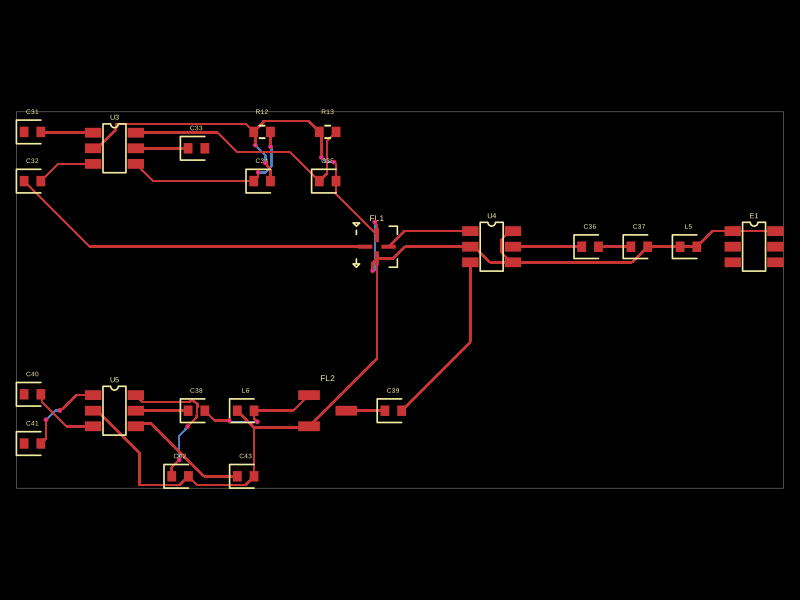 Similar packageMustafaMulla29/CC3235SF-tsxThis code defines a PCB layout with RF front-end components including RF switches (RTC6608OSP), band-pass filters, a diplexer, matching capacitors and inductors, and an antenna, all arranged to match a specific schematic for high-frequency radio signal routing.
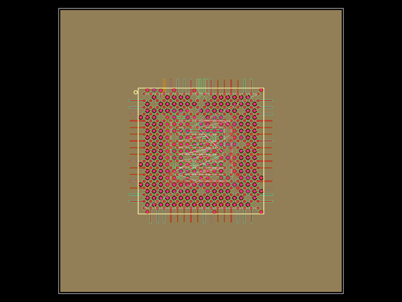 Discover something new0hmX/am3352This code defines a six-layer printed circuit board (PCB) design with a TI AM3352 microprocessor package, including precise pin mapping, power plane definition, fixed component placement, and PCB layout visualization.