imrishabh18/pedometer
This code defines and assembles a simple radio receiver hardware circuit using specific imported capacitors, inductors, RF connectors, and oscillator components with precise footprints and schematic attributes.
- Version
- 1.1.3
- License
- unset
- Stars
- 0
review/fabrication-review.json
PCB
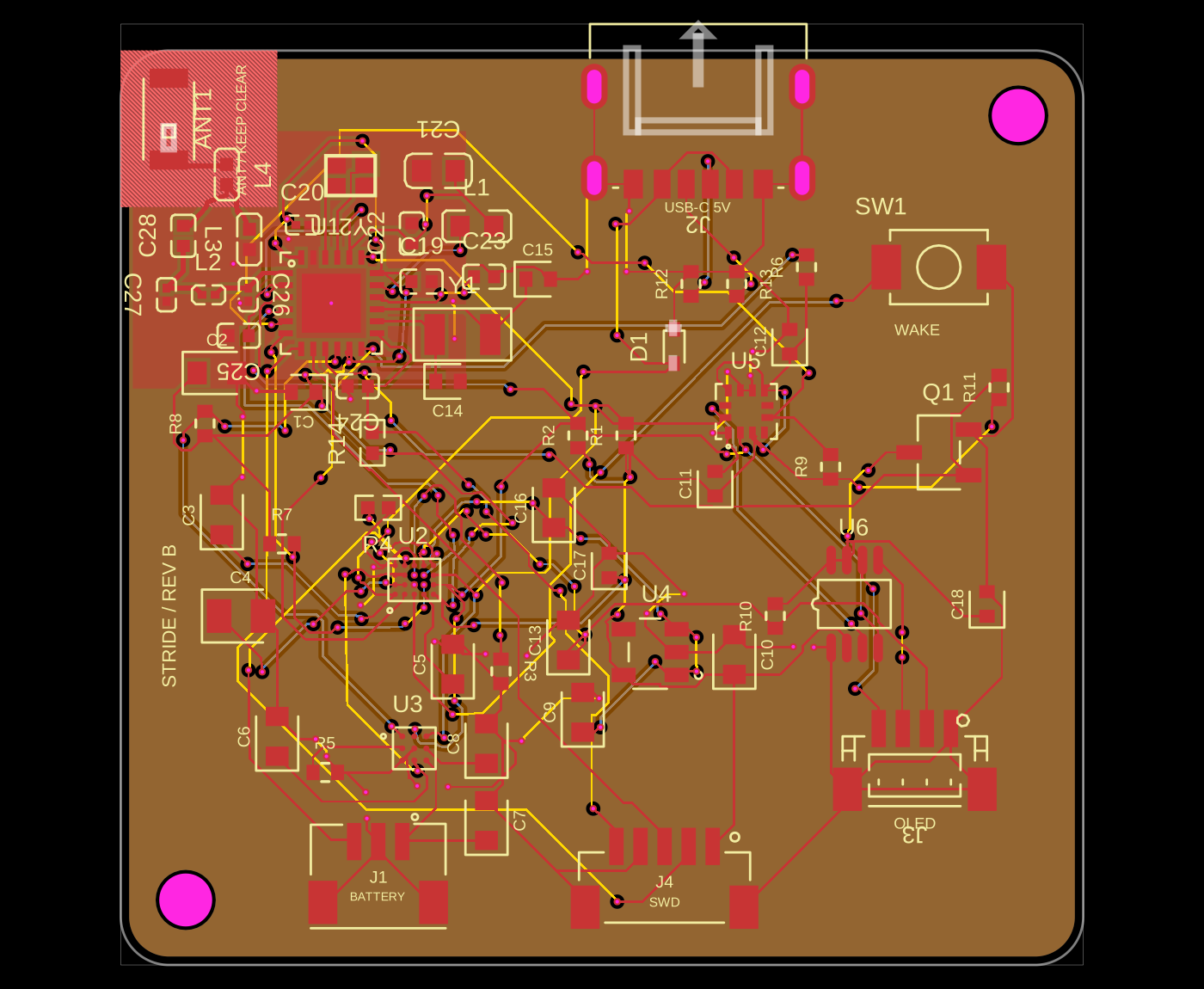
Schematic

{
  "date": "2026-09-07T08:43:32.193931+00:00",
  "status": "hold",
  "packageStatus": "ready-for-factory-cam-review",
  "package": "imrishabh18/pedometer",
  "localVersion": "1.1.3",
  "scope": "CAD and manufacturing export review of the bare CC2340R5 board; no factory process acceptance or physical prototype test has been obtained.",
  "circuitSha256": "384dff968fe32973bb6b1736216a0d754ce44283f269d087da7546204ef430cd",
  "manufacturingCircuitSha256": "b59631c17cfc05992d3e8f93d93082f429d3cae881ba66667ec9f0b55b1f256d",
  "findings": [
    {
      "id": "PAD-01",
      "status": "resolved",
      "title": "JLCPCB rejected passive footprints",
      "resolution": "Replaced all 12 rejected references and four additional passives sharing the custom footprint function with exact JLCPCB/EasyEDA imports. All 32 pad shapes, dimensions, pitches and pin assignments match the untouched imports; copper, mask and paste are verified in the exported Gerbers. Electrical values, part numbers and netlist are unchanged.",
      "evidence": "review/imported-footprint-audit.json; review/passive-gerber-audit.json; docs/footprint-correction.md"
    },
    {
      "id": "CAD-01",
      "status": "resolved",
      "title": "Fully routed board and programming connector",
      "resolution": "Fresh placement/routing checks, source-trace completeness, port connectivity and trace continuity all pass. All five J4 signals reach the MCU; reset bias is verified. SWCLK is routed in a dedicated top-only autorouting phase.",
      "evidence": "review/routing-completeness.json; review/programming-check.json"
    },
    {
      "id": "FAB-01",
      "status": "resolved",
      "title": "Physical drill spans and duplicate hits",
      "resolution": "Unpatched Gerber exporter 0.0.104 emits 163 unique through-vias, four plated USB-C slots and two NPTH holes. No blind/buried or duplicate drill hits.",
      "evidence": "review/drill-export-audit.json"
    },
    {
      "id": "FAB-02",
      "status": "resolved",
      "title": "Copper and drill clearances",
      "resolution": "Minimum pad-to-trace 0.114991 mm; trace-to-trace 0.114874 mm. Minimum drill-to-pad 0.209796 mm; drill-to-trace 0.212264 mm. No drill clearance violation below 0.20 mm; antenna keepout/pour intersection is zero.",
      "evidence": "review/copper-clearance.json; review/fabrication-metrics.json"
    },
    {
      "id": "ASM-01",
      "status": "resolved",
      "title": "BGA via-in-pad policy",
      "resolution": "BGA via-in-pad is permitted. The tscircuit FanoutSolver validates seven interior escapes across U2/U3. Current drill/land overlap counts by component: {'U2': 4, 'U1': 1}. No manual via JSX elements are present.",
      "evidence": "review/bga-via-inventory.json; bga-fanout.ts"
    },
    {
      "id": "BOM-01",
      "status": "resolved",
      "title": "PCB passive procurement",
      "resolution": "All 62 PCB components have exact MPNs and JLCPCB codes. Stock was not revalidated for this revision. External battery, NTC, display and cable sourcing are separate.",
      "evidence": "review/jlc-bom.csv"
    },
    {
      "id": "DOC-01",
      "status": "resolved",
      "title": "Printable fabrication silkscreen",
      "resolution": "Dense top references are retained in the assembly drawing. Fabrication uses four underside labels at 1.7 mm height and 0.153 mm stroke; copper and drill positions are preserved.",
      "evidence": "manufacturing.ts; review/manufacturing/B_SilkScreen.gbr"
    },
    {
      "id": "ASM-02",
      "status": "open",
      "severity": "factory-acceptance",
      "title": "Filled/capped vias, BGA mask, stencil and panel process",
      "requiredAction": "Approve resin-filled, planarized, copper-capped vias for all 163 plated vias (5 total drill/land overlaps). U2's 0.30 mm via annuli with 0.23 mm mask openings leave 0.035 mm radial overlap, below TI's illustrated 0.05 mm SMD overlap; explicit process acceptance is needed. Other BGA openings retain at least 0.119796 mm mask bridge. Approve the common/stepped stencil, ENIG and handling panel.",
      "evidence": "docs/assembly-requirements.md; review/bga-aperture-audit.json"
    },
    {
      "id": "RF-01",
      "status": "open",
      "severity": "factory-acceptance",
      "title": "RF impedance and stackup confirmation",
      "requiredAction": "Factory CAM must confirm a four-layer, 1.0 mm stackup compatible with the routed 0.20 mm top RF feed, its coplanar spacing and In1_Cu ground reference at 50 ohms. Return geometry changes for rerouting. Antenna tuning, oscillator calibration and range testing follow on prototypes.",
      "evidence": "docs/bare-cc2340r5.md; docs/assembly-requirements.md"
    }
  ],
  "references": [
    "https://www.ti.com/lit/ds/symlink/cc2340r5.pdf",
    "https://www.ti.com/lit/ds/symlink/bq25150.pdf",
    "https://www.ti.com/lit/ds/symlink/bq27427.pdf",
    "https://jlcpcb.com/capabilities/pcb-capabilities"
  ]
}
Related Packages
 More from this authorimrishabh18/test-pcmThis code defines a 10mm by 10mm electronic circuit board containing a single pin-row chip with an associated 3D CAD model of the "MachineContactMedium" component.
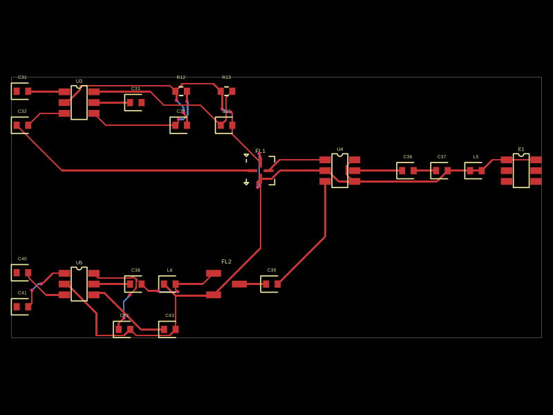 Similar packageMustafaMulla29/CC3235SF-tsxThis code defines a PCB layout with RF front-end components including RF switches (RTC6608OSP), band-pass filters, a diplexer, matching capacitors and inductors, and an antenna, all arranged to match a specific schematic for high-frequency radio signal routing.
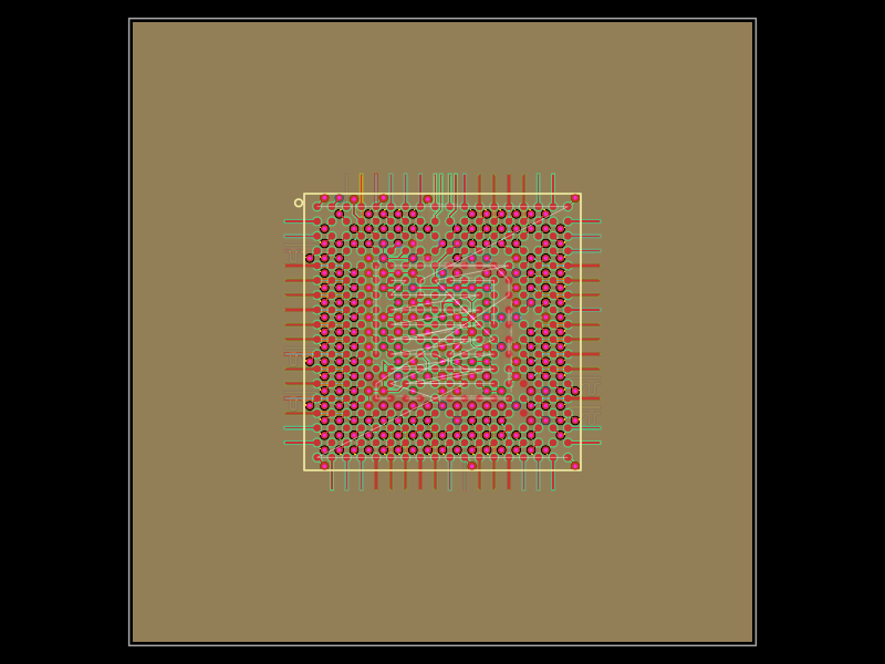 Discover something new0hmX/am3352This code defines a six-layer printed circuit board (PCB) design with a TI AM3352 microprocessor package, including precise pin mapping, power plane definition, fixed component placement, and PCB layout visualization.