imrishabh18/pedometer
This code defines and assembles a simple radio receiver hardware circuit using specific imported capacitors, inductors, RF connectors, and oscillator components with precise footprints and schematic attributes.
- Version
- 1.1.3
- License
- unset
- Stars
- 0
docs/footprint-correction.md
# Passive footprint correction — local v1.1.3

JLCPCB rejected C21, L1, C19, C25, C23, C24, C28, R4, R14, C22, L3 and L4 because their PCB pads did not match the selected packages. The prior design assigned supplier part numbers but used a hand-sized `radioFootprint` function. Assigning a BOM code did not import its pad geometry.

All 12 rejected references now use the corresponding JLCPCB/EasyEDA footprint imported with `tsci import <code> --jlcpcb --use-exact-footprint`. C20, C26, C27 and L2 shared the same custom function and were corrected too. The function has been removed. Imported source files are unmodified and their SHA-256 hashes are recorded in `review/footprint-import-provenance.json`.

The MCU, nearby crystal/load components and radio passives were repositioned to clear the imported courtyards. The whole board was rerouted. Electrical values, MPNs, JLCPCB codes, net assignments, board dimensions and clearance rules remain unchanged. RF and crystal routes remain on top copper without vias; RF trace records remain below 6 mm.

| References | JLCPCB code | Manufacturer part number | Imported pad width × height (mm) | Pad-center pitch (mm) |
|---|---|---|---|---|
| C19, C22, C24, C25 | C1525 | CL05B104KO5NNNC | 0.499999 × 0.540004 | 0.840232 |
| C21 | C2959727 | GRM188Z71A106KA73D | 0.799998 × 0.899998 | 1.400048 |
| L1 | C713281 | LQM18DN100M70L | 0.799998 × 0.864006 | 1.399794 |
| C23 | C52923 | CL05A105KA5NQNC | 0.499999 × 0.540004 | 0.840232 |
| C28 | C76898 | GJM1555C1H1R0BB01D | 0.499999 × 0.540004 | 0.840232 |
| R4 | C25744 | 0402WGF1002TCE | 0.565658 × 0.540004 | 0.865632 |
| R14 | C25741 | 0402WGF1003TCE | 0.565658 × 0.540004 | 0.865632 |
| L3 | C77108 | LQG15HS2N7S02D | 0.540004 × 0.540004 | 0.839978 |
| L4 | C77109 | LQG15HS3N9S02D | 0.540004 × 0.540004 | 0.839978 |
| C20 | C76934 | GRM033R61A104KE15D | 0.368427 × 0.324002 | 0.548640 |
| C26, C27 | C237515 | GJM0335C1H1R5BB01D | 0.368427 × 0.324002 | 0.548640 |
| L2 | C206433 | LQP03TN2N8B02D | 0.368427 × 0.324002 | 0.548640 |

Dimensions above use the unrotated library orientation. See `assembly/footprint-comparison.svg` in the CAM package for an equal-scale comparison.

## Verification

- Full build, TypeScript check, DRC and independent routing/connectivity checks pass.
- `tsci check`: zero errors and zero warnings; shorts check passes.
- All 18 regression tests pass, including RF/clock routing and manufacturing copper preservation.
- All 16 imported components / 32 pads match the raw imports, including physical pin numbers.
- All 32 corrected pads have the expected copper, soldermask and paste flashes in the exported Gerbers.
- All 62 PCB references have JLCPCB codes; all 62 CPL positions/rotations match the same manufacturing circuit.
- Copper and through-drill clearance audits pass. The minimum pad-to-trace clearance is 0.114991 mm; trace-to-trace is 0.114874 mm.

## Replacement files for JLCPCB

Use `pedometer-gerbers.zip`, `assembly/BOM.csv` and `assembly/CPL.csv` from this package together. They replace the rejected PCB geometry and its prior placement files. A BOM-only replacement does not correct already fabricated copper.

Send the complete package for CAM review, including the comparison drawing. The imported library and exported copper are now consistent; JLCPCB still needs to confirm its assembly-library fit and rotations. The existing filled/capped-via, BGA mask/stencil and RF-stackup acceptance items remain recorded in `docs/assembly-requirements.md` and `docs/fabrication-review.md`. This package does not claim factory acceptance or physical prototype validation. Stock was not rechecked for this revision.

Version 1.1.3 contains the corrected passive footprints and the matching fabrication files.
Related Packages
 More from this authorimrishabh18/test-pcmThis code defines a 10mm by 10mm electronic circuit board containing a single pin-row chip with an associated 3D CAD model of the "MachineContactMedium" component.
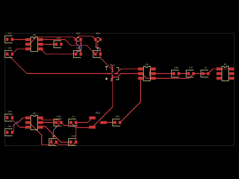 Similar packageMustafaMulla29/CC3235SF-tsxThis code defines a PCB layout with RF front-end components including RF switches (RTC6608OSP), band-pass filters, a diplexer, matching capacitors and inductors, and an antenna, all arranged to match a specific schematic for high-frequency radio signal routing.
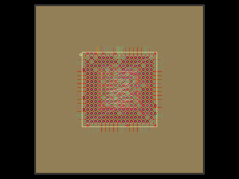 Discover something new0hmX/am3352This code defines a six-layer printed circuit board (PCB) design with a TI AM3352 microprocessor package, including precise pin mapping, power plane definition, fixed component placement, and PCB layout visualization.